Key Takeaways:
A gate shop drawing lets your shop build the gate without a single follow-up question. Most costly gate mistakes start with an incomplete drawing, not a bad weld.
- Dimension the clear opening, the gate leaf, and the hinge and latch gaps separately
- Note ground clearance, drive slope, member wall thickness, and infill spacing
- Check that gate width plus gaps equals the clear opening before you cut
- Build the bill of materials from the drawing, not from memory
A shop drawing for an iron gate is a dimensioned, to-scale document that tells the shop exactly what to build: overall gate size, frame member sizes, infill spacing, hardware locations, and a bill of materials listing every piece with its cut length and angle. It differs from a design sketch in one critical way. A sketch shows the customer what the gate will look like, while a shop drawing lets a fabricator build it without asking a single follow-up question.
Most shops that struggle with gates aren't struggling with welding. They're struggling because the drawing was incomplete, and the missing information got filled in at the bench by guesswork.
Here's what a complete gate shop drawing contains and how to produce one.
What goes on a gate shop drawing
The elevation view. This is the main view, the gate as you'd see it standing in front of it. It carries overall width and height, the top rail profile (straight, arched, or scrolled), picket or baluster spacing, and the location of any decorative elements.
The plan view. Looking down from above. This is where swing direction, hinge side, post positions, and the relationship between gate leaf and opening get established. For a double gate, the plan view is where you show how the leaves meet and which one carries the drop rod.
Dimensions that separate opening from gate. This is the single most common source of costly errors. The clear opening between posts, the actual gate leaf width, and the gaps at hinge and latch are three different numbers. A gate built to the opening dimension will not fit the opening.
Ground clearance. Driveways slope. A gate that clears the ground at the closed position may bind at 45 degrees open if the drive rises. Note the clearance and the drive slope, or note that the site is level.
Frame member sizes and wall thickness. "2-inch square tube" isn't enough. 2" x 2" x 11ga behaves very differently from 2" x 2" x 14ga on a 16-foot double drive gate.
Infill spacing. Give the picket size, the on-center spacing, and the count. If the gate is anywhere near a pool enclosure or serves as a guard, spacing is governed by code. The 4-inch sphere rule is the common benchmark, but verify against your local adopted code before you cut.
Hardware callouts. Hinge type and quantity, latch, drop rod, cane bolt, and, if it's automated, the operator, the mounting bracket location, and whether the leaf needs reinforcement at the arm attachment point.
The bill of materials. Every part, every quantity, every length, every angle cut.
Step by step
- Confirm the field measurements. Measure the clear opening at the top and the bottom, and measure the diagonal. Openings are rarely square. Note the drive slope and the direction of fall. If the posts aren't set yet, you're specifying them rather than measuring them, and that needs to be explicit on the drawing.
- Establish post size from gate weight, not habit. A heavy ornamental leaf on an undersized post will sag within a season. Work out the approximate leaf weight from the frame and infill before you commit to a post.
- Lay out the frame. Perimeter first, then intermediate rails. Decide now whether corners are mitered or butt-welded, because it changes every cut length in the frame.
- Set the infill. Divide the inside frame dimension by the desired spacing and adjust so the end gaps match the intermediate gaps. Uneven end gaps are the most visible tell of a rushed layout, and customers notice them from the street.
- Place hardware. Position hinges relative to the top and bottom rails, put the latch at a usable height, and center the drop rod on the meeting stile for a double gate.
- Generate the bill of materials. Pull quantities and lengths off the drawing, not off memory. Include the angle for every non-square cut.
- Check it against the opening one more time. Gate width plus hinge gap plus latch gap equals clear opening. If that equation doesn't balance, the drawing is wrong.
The mistakes that cost the most money
Drawing the gate at the opening dimension. Covered above, and it's still the number one cause of a gate going back on the truck.
Forgetting the diagonal. A frame that's square on paper and racked in the fixture produces a gate that won't latch. Include the diagonal dimension on the drawing so the person setting up the table has something to check against.
Leaving the arch undimensioned. "Arched top" is not a dimension. Give the rise at the center and the radius, or give three points on the curve.
Not accounting for the operator. Automated gates need reinforcement where the arm attaches. If that isn't on the drawing, it gets welded on later, badly, after the finish is already applied.
Quoting off the sketch. Material takeoffs done from a design sketch instead of a dimensioned drawing are guesses. On ornamental work, where castings and scrollwork can be a meaningful share of material cost, a guess is where margin disappears.
By hand versus automated
A competent detailer can draw a straightforward single gate by hand in perhaps an hour, and a complex double drive gate with scrollwork and castings in considerably longer. The bill of materials then has to be counted off that drawing by hand, which is where transcription errors enter.
Purpose-built fabrication CAD changes the math. Instead of drawing each picket, you enter the gate dimensions, pick the style and materials, and the software generates the geometry and the bill of materials together. Because the parts list is derived from the drawing rather than counted off it, the two can't disagree.
This matters most on revisions. When a customer asks to widen the gate by eight inches, hand-drawn work means redrawing the infill, recounting the pickets, and rebuilding the cut list. Parametric work means changing one dimension.
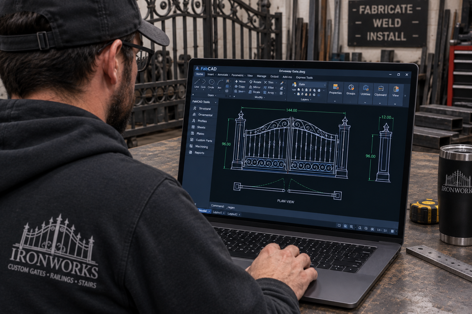
FabCAD was built for exactly this. It's 2D CAD on Autodesk technology, customized for ornamental metal, with automation that draws gates, fences, and railings from your dimensions and produces the bill of materials at the same time. The design library carries more than 16,000 castings and forgings from ten manufacturers, pre-drawn to scale and already tied into the takeoff, so a decorative element you drop into a gate shows up in the parts list with the right part number.